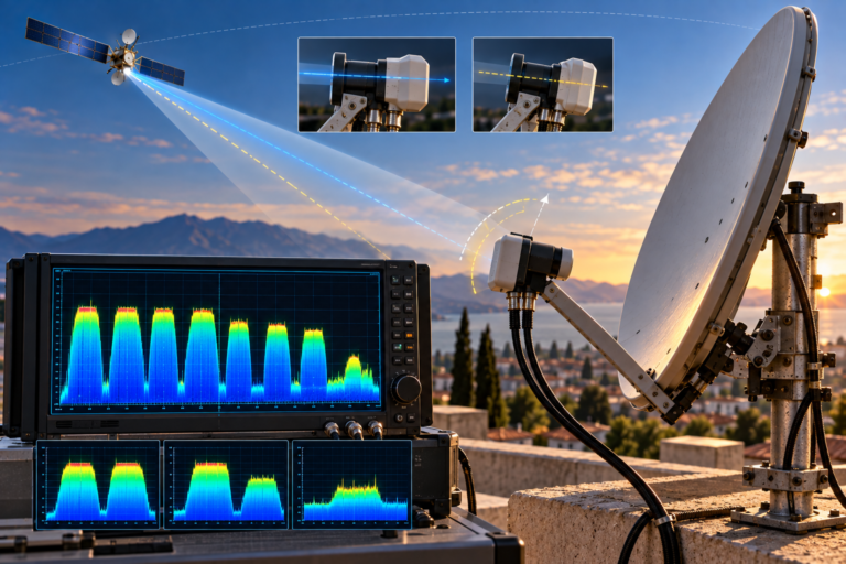
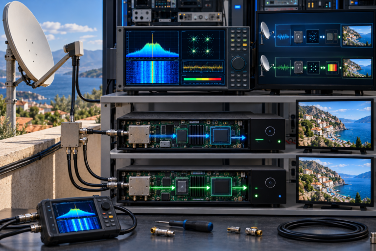
Why Hot Bird Reception Changes After an LNB Swap
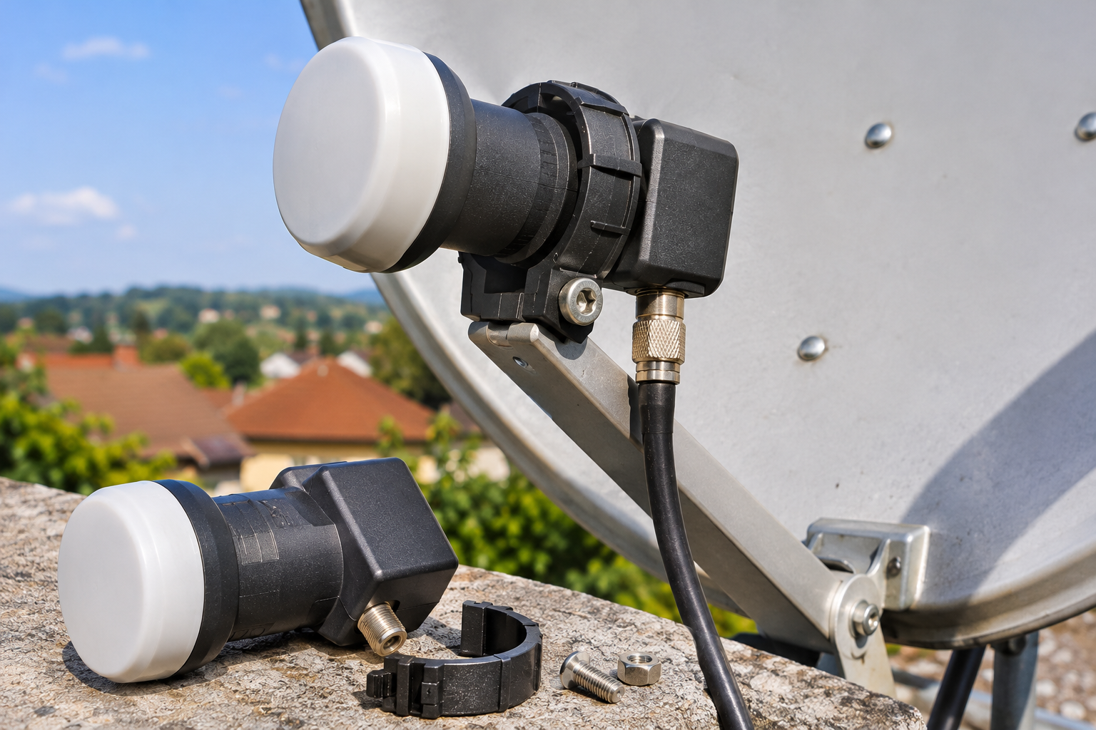
Your Hot Bird 13°E dish worked normally until you replaced the LNB. Now several transponders are weaker, some channels freeze, and others refuse to lock. The new LNB may even advertise better specifications than the old one. So why did reception become worse immediately after the upgrade?
An LNB replacement changes more than the electronic component at the end of the feed arm. Its mounting position, rotation angle, feed geometry, cable connection, and compatibility with the receiver can all change during the installation. Even a small disturbance to an already marginal system can reveal problems that were previously hidden. The most reliable diagnosis is to identify exactly what changed during the swap and test each possibility without disturbing the rest of the installation.
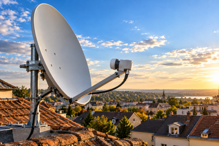
Hot Bird 13°E reception depends on a correctly aligned reflector, suitable feed assembly, compatible LNB, healthy coaxial connection, and properly configured receiver. If reception changes immediately after replacing the LNB, that timing is valuable evidence, but it does not prove that the replacement unit is defective. Mechanical installation differences and disturbed connections must be investigated first.
What Actually Changes During an LNB Swap?
Replacing an LNB appears straightforward: disconnect the coaxial cable, loosen the mounting clamp, remove the old unit, and install the replacement.
However, several important variables can change during those steps.
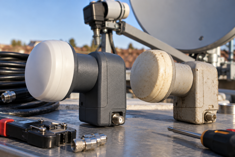
The new LNB may sit at a different depth inside the holder. Its polarization angle may not match the original. The cable may be bent or disturbed, and the feed arm may move slightly under mechanical pressure.
If the new model uses different operating characteristics, the receiver configuration may also need attention.
These changes should be considered separately rather than treated as one general LNB performance problem.
Why the Original Installation Is a Valuable Reference
If the old unit provided stable reception immediately before replacement, its performance establishes a useful baseline.
That baseline is strongest when actual measurements were recorded before the swap.
Useful information includes:
- Which transponders locked reliably.
- Measured MER and C/N where available.
- The original LNB mounting depth and rotation.
- Receiver oscillator and switching settings.
- The original cable and output connections.
Without this information, it becomes harder to distinguish an equipment difference from an installation change.
Why a Few Millimeters of LNB Movement Can Affect Reception
The feed assembly collects energy concentrated by the satellite reflector.
Its position relative to the reflector influences how efficiently that energy is received.
When an LNB is replaced, the effective receiving position may change even if the mounting collar appears to occupy the same location.
The Difference Between the Collar and the Feed Phase Center
The mounting collar is a mechanical reference point. It does not necessarily identify the feed’s effective electromagnetic phase center.
Different LNB designs can have different feedhorn dimensions and internal geometries.
Consequently, installing two models at identical collar positions does not guarantee identical antenna performance.
A small mounting-depth adjustment may improve or reduce reception depending on the reflector and feed design.
Why Marginal Transponders Reveal the Problem First
A carrier with comfortable reception margin may remain stable after a minor reduction in feed efficiency.
Another carrier operating closer to its decoding threshold may begin freezing or lose lock.
This can make the replacement appear to affect only certain frequencies.
The pattern does not necessarily mean the new LNB is defective at those frequencies.
How to Check Mounting Depth
Start with the antenna manufacturer’s intended mounting arrangement.
Verify that the feed is seated securely and that the correct holder or adapter is being used.
If the installation permits adjustment, a qualified installer can evaluate small controlled changes while monitoring several representative carriers.
Do not push the LNB randomly forward or backward based on one receiver percentage.
How LNB Skew Can Change During Replacement
Skew describes the rotational orientation of the receiving feed relative to the incoming linearly polarized signal.
The correct adjustment depends on the receiving location, satellite geometry, and antenna arrangement.
Replacing an LNB can unintentionally change its rotation angle.
Why the Original Angle Matters
Some installers use the old LNB’s visible orientation as a starting reference for the replacement.
That can be useful, but exterior markings and housing shapes are not always directly comparable between models.
Final polarization alignment should therefore be evaluated using the appropriate antenna geometry and actual measurements.
What Incorrect Skew Can Cause
Poor polarization alignment can reduce isolation between the desired signal and energy arriving on the orthogonal polarization.
The resulting interference may reduce MER on selected transponders.
Depending on the available margin, some channels may remain usable while others become unstable.
However, incorrect skew should not be confused with an electrical polarization-switching failure.
A receiver that cannot select the required horizontal or vertical signal through its control path will not be repaired simply by rotating the LNB.
LNB skew, voltage-controlled polarization selection, and feed mounting depth are three different variables. Each can affect reception, but adjusting one does not automatically correct faults involving the others.
Did the Dish or Feed Arm Move During the LNB Swap?
Removing an LNB can place force on the feed arm, mounting clamp, or nearby cable supports.
If the antenna structure is poorly secured, that force may alter its position.
The result can resemble a faulty replacement LNB even though the actual problem is changed antenna alignment.
Why Small Mechanical Changes Matter
A parabolic dish provides its highest directional gain near its intended pointing direction.
Moving away from that direction generally reduces receiving gain.
The amount of loss depends on the reflector’s beamwidth and the size of the pointing error.
Transponders with less reception margin may fail first.
What to Inspect
Check that the feed arm is properly secured, the LNB clamp is stable, and the reflector mounting hardware has not moved.
Look for loose brackets, visible deformation, or movement under light mechanical loading.
Do not attempt rooftop inspection without appropriate access and fall-protection precautions.
If movement is suspected, a professional alignment check is more useful than immediately replacing the new LNB.
Cable and F-Connector Problems Introduced During Replacement
The coaxial connection is often disturbed during an LNB swap.
A connector that worked before removal may not provide the same electrical contact after being disconnected, bent, or reattached.
Loose or Damaged F-Connectors
A poorly seated F-connector, damaged center conductor, or deteriorated cable termination can affect both RF transmission and LNB control.
Depending on the fault, the receiver may lose all carriers or only selected groups.
A cable that has been pulled tightly may also place mechanical stress on the LNB socket.
Moisture and Weatherproofing
Outdoor satellite connections require appropriate protection against water ingress.
Replacing an LNB can disturb an existing weather seal.
If the connection is left exposed, moisture may introduce intermittent or persistent faults later.
Inspect the connector and restore weatherproofing using suitable manufacturer-approved materials.
Why DC Switching Can Be Affected
In a conventional universal-LNB installation, the coaxial cable carries both the converted RF signal and the receiver’s LNB power and control information.
Excessive resistance or unreliable contact can interfere with operation.
For example, a switching state may fail to reach the LNB correctly under load.
The resulting symptom may look like missing horizontal, vertical, or high-band transponders.
Switch off and disconnect the relevant receiver and powered distribution equipment before removing or reconnecting coaxial cables. Do not short the center conductor to the cable shield. Powered RF and voltage measurements should be performed only with suitable test equipment and manufacturer-approved procedures.
Receiver Settings That Must Match the Replacement LNB
Not every LNB uses the same frequency-conversion or output architecture.
Before comparing reception quality, verify that the receiver configuration is appropriate for the installed hardware.
Universal LNB Oscillator Settings
A conventional European universal Ku-band LNB commonly uses nominal local oscillator frequencies of 9,750 MHz and 10,600 MHz.
The receiver uses these values to calculate the intermediate frequency required to tune a selected satellite transponder.
If the replacement uses a different conversion scheme, retaining inappropriate settings can prevent proper acquisition.
Band and Polarization Selection
Conventional universal LNBs generally use nominal 13V and 18V control states for vertical and horizontal polarization.
A 22 kHz control tone is commonly used for high-band selection.
A mismatch between the installed equipment and receiver settings can make entire groups of transponders unavailable.
Different LNB Output Architectures
A universal Single, Twin, or Quad LNB is not automatically interchangeable with a Quattro unit intended for compatible multiswitch distribution.
Similarly, SCR and dCSS equipment require suitable receiver settings and user-band assignments.
A hardware replacement should preserve the intended distribution architecture unless the installation is deliberately being redesigned.
For a post-swap investigation, identify the new unit’s exact model and specifications before making assumptions about its compatibility.
Why a New LNB Can Produce Different Signal Quality
Even after correct mounting and configuration, two compatible LNBs may produce different measured RF performance.
That difference can result from noise characteristics, gain response, oscillator performance, manufacturing tolerances, or equipment condition.
Noise Figure and Overall Receiver Performance
An LNB’s noise contribution influences the receiving system’s overall sensitivity.
However, a lower advertised noise figure does not guarantee better performance in every installation.
Feed efficiency, oscillator stability, conversion characteristics, and downstream receiver conditions also matter.
Higher Gain Is Not Always Better
A replacement LNB may provide more conversion gain than the old unit.
This can increase the signal level delivered to the receiver, but it does not automatically improve MER or C/N.
Excessive downstream levels can also create problems in some receiving or distribution systems.
The correct comparison should focus on usable carrier quality rather than advertised gain alone.
Oscillator Stability and Frequency Offset
Differences in local oscillator accuracy can affect the converted carrier’s frequency position.
Receivers normally tolerate frequency offsets within supported acquisition and tracking ranges.
However, excessive offset or instability can make selected carriers difficult to acquire.
A measured frequency offset provides stronger evidence than assuming that slow locking indicates a defective LNB.
What Different Post-Swap Symptoms Reveal
| Observed Pattern | Possible Explanation | First Useful Check |
|---|---|---|
| All transponders disappear immediately after replacement | Connection, compatibility, power, or pointing problem | Verify model, wiring, settings, and RF path |
| Only marginal carriers become weaker | Feed position, skew, pointing loss, or RF performance difference | Compare MER on verified carriers |
| Horizontal or vertical carriers disappear | Polarization selection, skew, or electrical fault | Separate switching tests from feed alignment |
| Only high-band carriers fail | Band switching or oscillator configuration | Check LO settings and applicable 22 kHz control |
| Signal worsens when the coax is disturbed | Loose connector or damaged cable | Inspect and test the connection safely |
| Signal changes after tightening the feed clamp | Feed movement or mounting instability | Recheck mounting depth and skew |
| Original LNB repeatedly restores reception | Possible replacement incompatibility or performance difference | Perform a controlled A/B/A test |
| Channel entries disappear only after rescanning | Database clearing combined with failed rediscovery | Check RF lock and scan settings |
The table identifies likely investigation paths. No single symptom proves that the replacement LNB is defective.
How to Perform a Controlled A/B/A LNB Comparison
A repeatable comparison is more reliable than testing the new LNB once and immediately declaring it worse.
One practical method is an A/B/A test.
Test A: Original LNB
Record measurements with the original compatible LNB.
Use several currently verified transponders representing relevant frequency ranges and polarizations.
Record lock status, C/N, MER, and applicable error measurements.
Test B: Replacement LNB
Install the replacement carefully, preserving other installation variables wherever possible.
Use the correct receiver settings and verify its feed position and skew.
Repeat the measurements using the same equipment and transmission parameters.
Repeat Test A
Reinstall the original unit and determine whether the earlier baseline returns.
Repeatable improvement with the old LNB strengthens the evidence for a difference involving the new installation or hardware.
However, the conclusion remains limited if the two units cannot be positioned equivalently or if the antenna moves during each exchange.
A: Original LNB and baseline measurements.
B: Replacement LNB under comparable conditions.
A: Original LNB reinstalled to verify repeatability.
Use the same verified transponders and record any differences in mounting geometry, receiver configuration, and weather conditions.
Step-by-Step: Restore Hot Bird Reception After an LNB Swap
Step 1: Stop Changing Multiple Settings
Do not immediately move the dish, change LNB oscillator settings, and rescan the receiver at the same time.
Doing so makes it difficult to determine which change caused or corrected the problem.
Step 2: Confirm the Replacement Model
Read the new LNB’s specifications and confirm its output architecture, frequency range, oscillator settings, and compatibility.
Compare these characteristics with the original unit and the receiving system.
Step 3: Inspect the Installation
With the relevant equipment disconnected from power, inspect the feed clamp, coaxial connector, cable strain, and weatherproofing.
Check for obvious movement or damage introduced during replacement.
Step 4: Verify Receiver Configuration
Ensure that the receiver is using the correct LNB type, oscillator values, and switching arrangement.
Preserve the existing channel database while troubleshooting.
Step 5: Test Known-Good Transponders
Use currently verified Hot Bird carriers rather than relying on one saved television channel.
Where possible, compare representatives from both polarizations and frequency bands.
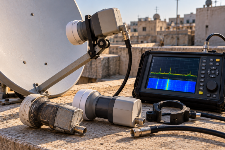
Step 6: Measure Reception Quality
Use MER, C/N, and appropriate error measurements to evaluate changes.
Consumer receiver strength percentages are not standardized and may not reveal the actual problem.
Step 7: Evaluate Feed Geometry
If configuration and connections are correct, examine mounting depth, skew, and alignment using controlled adjustments.
Professional test equipment is preferable when optimizing marginal carriers.
Step 8: Repeat the Original-LNB Test if Necessary
Where safe and practical, reinstall the original unit and repeat the same measurements.
If the original reliably restores reception and the replacement does not, investigate compatibility, manufacturing defects, or genuine RF performance differences.
Confirm LNB model → Inspect connections → Verify receiver settings → Test known carriers → Measure quality → Check mounting and skew → Compare old and new hardware.
Only replace or return the new LNB after the evidence supports an actual hardware problem.
Why Rescanning After an LNB Swap Can Make the Problem Worse
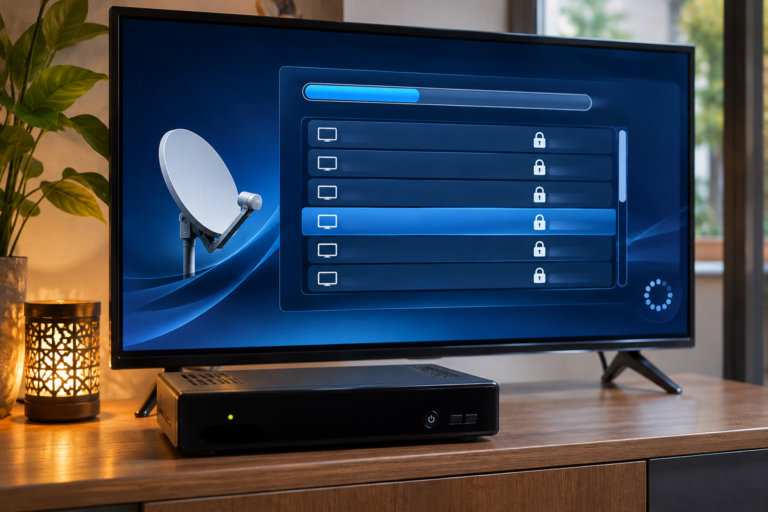
When channels disappear following an LNB replacement, users often attempt a full satellite scan.
However, scanning does not correct a poorly positioned feed, incompatible LNB, damaged cable, or failed switching path.
A scan simply attempts to discover services from transponders that the receiver can successfully acquire.
If the new installation cannot receive certain carriers, a scan with a database-clearing option may remove their previously stored channel entries.
The result can make the problem appear more severe.
Our related guide, Why Hot Bird Channels Vanish After a Receiver Scan, explains how clearing options, scan filters, and incomplete service discovery can change the receiver’s saved channel list.
For an LNB replacement problem, confirm stable RF lock before performing a destructive channel scan.
Reality Check: A New LNB Is Not Automatically a Better LNB
A replacement LNB may advertise lower noise, higher gain, or newer technology, but those claims alone do not establish better performance in a particular installation.
Its mechanical geometry may differ from the original, and its electronic characteristics may interact differently with the receiver and distribution network.
At the same time, a reception problem appearing immediately after replacement may result from a disturbed connector, changed skew angle, or feed-position error rather than defective electronics.
The timing of the problem identifies the swap as the event to investigate. It does not identify which part of the swap caused the fault.
Final Verdict
If Hot Bird 13°E reception changes immediately after an LNB swap, begin by isolating the mechanical and electrical changes introduced during installation.
Mounting depth, feed geometry, skew, cable connections, receiver settings, and accidental dish movement can all affect reception.
Even compatible LNBs may perform differently because of noise characteristics, oscillator behavior, or manufacturing tolerances.
The most reliable approach is to verify compatibility, measure representative carriers, and compare the original and replacement units under controlled conditions.
Restore the RF system before rescanning services. A successful repair should improve repeatable carrier-quality measurements rather than merely increase the receiver’s displayed signal-strength percentage.
Frequently Asked Questions
Why is my Hot Bird signal weaker after changing the LNB?
The replacement may sit at a different feed position, have incorrect skew, use incompatible settings, or expose a disturbed cable connection. Genuine differences in LNB performance are also possible. Measure the same transponders before deciding which cause applies.
Can moving an LNB a few millimeters affect reception?
Yes. Feed position influences reflector illumination and receiving efficiency. The actual effect depends on antenna geometry, feed design, and the system’s available reception margin.
Should the new LNB use the same skew angle as the old one?
The original orientation is a useful starting reference, but different housings and markings may not be directly comparable. Final skew alignment should be verified for the installation using appropriate measurements.
Can a damaged F-connector cause missing channels after an LNB replacement?
Yes. An unreliable connector can introduce RF loss or affect LNB power and switching. Inspect the connection with equipment safely disconnected, and use suitable test instruments where necessary.
Why does the old LNB work better than a new one?
The new unit may have different feed geometry, electronic performance, or compatibility requirements. A controlled comparison is needed to distinguish a defective replacement from mounting and configuration differences.
Will a full rescan fix reception after changing the LNB?
No, not when the underlying issue prevents carrier lock. Rescanning can update channel information, but it cannot repair incorrect feed position, damaged connections, or incompatible switching hardware.
How can I tell whether the new LNB is defective?
Verify compatibility, installation geometry, cables, and receiver settings. Then compare representative carrier measurements using the original and replacement units under equivalent conditions. Repeatable differences provide stronger evidence than a single signal-strength reading.